Path Metadata in Beacons
Introduction
When selecting end-to-end SCION paths, it is useful to have information about the properties of the available paths, such as information about the expected latency or the “type” of the traversed links.
This document describes how metadata can be included in an optional extension
of the Path Construction Beacons (PCBs), called StaticInfoExtension, so
that it can be used by applications on the end hosts in the path selection
process.
Static properties
We distinguish between static and dynamic properties of a path. Static properties remain valid over the course of its announced lifetime. The lifetime of a path typically is on the order of minutes to hours. Properties that can vary more quickly are considered dynamic.
As an example, the maximum possible bandwidth on each link of a path is static, as it will not change unless the underlying network infrastructure is modified. On the other hand, the bandwidth available to an application over this path is dynamic, as it depends on the current load on the network infrastructure along the path.
In the PCBs, we can naturally only include information about the static properties of a path.
Symmetry
SCION paths and path segments are reversible. The system described here does not allow representing values differing depending on the usage direction. Instead, we require that all metadata items represent quantities that are symmetric. If a path hop has e.g. different latency in the two directions we can just pick the more conservative estimate.
Path Segments with Metadata
SCION end-to-end paths are obtained by combining up to three (up, core and down)
path segments which correspond directly to a PCB. A path segment consists
of a series of ASEntrys, one for each AS. An ASEntry describes the
traversal of an AS for a specific pair of “ingress” and “egress” interfaces
(where ingress/egress refer to the dissemination direction of the beacon).
To describe the properties of all hops of a path, we will have to include
information about the links between the ASes (inter-AS hops), and also for
the hops from the ingress to the egress inside an AS (intra-AS hops). For
the intra-AS hops, it is however not enough to include only information about
the hop between the beacon ingress and egress interfaces – where two path
segments can be “joined” together, we have to ensure that the information about
the resulting intra-AS hop is contained in (at least) one of the ASEntrys.
The figures below illustrate the various ways in which segments can be combined to form end-to-end paths:
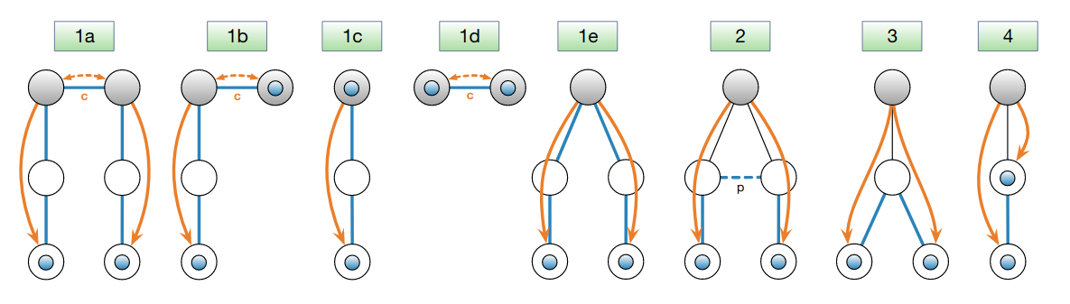
Combination of path segments to paths: the blue circles represent the end hosts; the shaded gray circles represent core ASes, possibly in different ISDs; blue lines without arrow heads denote hops of created forwarding paths; the dashed blue line denotes a peering link (labeled “p”); orange lines with arrows stand for PCBs and indicate their dissemination direction; dashed orange lines represent core beacons exchanged over core links (labeled “c”). All created forwarding paths in cases 1a-1e traverse the ISD core(s), whereas the paths in cases 2-4 do not enter the ISD core.
Representation in StaticInfoExtension
We use the following scheme, to ensure that each hop is described by (at least) one ASEntry.
We rely on symmetry and avoid some redundancy.
Each ASEntry includes information about:
the inter-AS hop at the egress interface
the intra-AS hop between egress and any (other)
CHILD-link interface with ID smaller than the egress interface, for shortcuts.the intra-AS hop between egress and any (other)
CORE-link interface, for up-core or core-down segment cross-overthe intra-AS hop between egress and any
PEER-link interface, and the inter-AS hop at anyPEER-interface
Path from 111 to 211, through core. Case 1a, above. |
Path from 111 to 211, via peering link. Case 2, above. |
Path from 111 to 112, with shortcut at 110. Case 3, above. |
Wire format
In the PCBs, the per-hop information is represented using the following
structure (extracted from proto/control_plane/v1/seg_extensions.proto):
This is the generalized Protocol Buffers-like description for a per-link
metadata item of type T (but Protocol Buffers does not actually have a
templates).
message HopMetadata<T> {
    // Information about the hop between construction-egress interface and the relevant other
    // interfaces. These are:
    // - construction-ingress interface (if any)
    // - sibling child interfaces,
    // - core interfaces, at start or end of a segment
    // - peer interfaces
    // The key is the interface identifier of the other interface.
    map<uint64, T> intra = 1;
    // Information about the hop between the local interface and the interface in the neighbor AS
    // for the relevant links. These are:
    // - link at construction-egress interface (if any)
    // - peer links
    // The key is the interface identifier of the local interface associated
    // with the link.
    map<uint64, T> inter = 2;
}
Note that some of the metadata types discussed below do not describe per-hop information but e.g. per-AS notes. These are much simpler to represent in the PCBs and don’t need to be discussed here.
Conflicts
When combining the information from all the path segments, information may be
available from more than one ASEntry. Therefore, it is possible to have
conflicting information, which must be considered when combining path segments.
The conflicts are resolved by selecting the most conservative value.
This conflict resolution procedure allows an AS to announce a more conservative value for the metadata of inter-AS links if it disagrees with the value announced by the upstream AS.
Authenticity, Integrity and Accuracy
The responsibility for providing all of this metadata lies with the individual ASes. There is no mechanism to enforce that this information is complete or accurate.
The beacon extensions are signed/verified based on the control plane PKI. This provides integrity and accountability for the provided metadata.
No AS can tamper with the metadata included in a beacon
The source of the metadata is visible and non-repudiable. Thus, if an AS was detected to be including false information, it can be held accountable by e.g. being added to a block list.
Metadata types
Latency
Latency describes the propagation delay between any two hops on the path. The advertised information describes the latency for an ideal idle state of the network infrastructure, i.e. it does not account for any variable delay due to queuing or processing.
Use cases of such information include:
Augment path selection policy in order to obtain low latency paths.
Bandwidth
Bandwidth describes the maximum bandwidth between any two hops on the path. The advertised information describes the bandwidth for an ideal idle state of the network infrastructure, i.e. it does not account for congestion.
Use cases of such information include:
Augment path selection policy, such that unsuitable paths can be excluded a priori.
Avoid connections that are prone to congestion due to a low-bandwidth bottleneck somewhere.
Geographic information
This describes the geographic position of each router on the path. The position is described as a GPS coordinate (latitude/longitude pair, in the WGS 84 datum) as well as an optional free-form civic address.
Use cases of such information include:
Can be used to augment path selection policies in order to ensure paths do not leave a particular area, or alternatively ascertain that they never cross territory that is considered “undesirable” by the user.
Can be used to provide users with information about the location of the entity they are communicating with (i.e. the endpoint on the other side of the path).
Informing network admins about router locations.
Cross-check or enhance latency information
Link Type
Link Type information gives a broad classification of the different underlying infrastructure used by inter-AS links.
For now it distinguishes three different types of links:
DIRECT: direct physical connectionMULTI_HOP: connection with local routing/switchingOPEN_NET: connection overlayed over publicly routed Internet
Use cases of such information include:
Mitigating security concerns.
Allowing users to select paths that e.g. avoid the open Internet.
Internal Hops
The Number of AS-internal hops counts the internal hops (e.g. internal IP routers) between the ingress and egress routers of any AS on the path.
Use cases of such information include:
Can be used to exclude undesirable paths from the selection.
Obtain a selection of efficient, low latency paths (especially when combined with Latency Information).
Note
A Note is simply a bit of plain text. Use cases of such information include:
Tool for network engineers to communicate interesting/important information to their peers as well as users.
Application Programming Interface
Applications will typically not interact with the raw information in the
StaticInfoExtension in the ASEntrys.
The path combinator (go/lib/infra/modules/combinator) is used to
extract (only) the relevant information from the individual ASEntrys
when combining path segments to a path.
The snet.PathMetadata struct contains the resulting path metadata.
Command Line Interface
scion showpaths displays the available extended path metadata if the
--extended/-e flag is provided.
The following values will be displayed in human readable form, provided they
are available:
Name |
Description |
|---|---|
Latency |
Total latency |
Bandwidth |
Bottleneck bandwidth |
Geo |
Sequence of geographical coordinates of routers along path, separated by |
LinkType |
The link type of each inter-AS connection along the path |
InternalHops |
Number of internal hops, per AS, in order of appearance on the path |
Notes |
The notes for each AS on the path |
Example Configuration
Let us look at an AS with three interfaces with IDs 1, 2, 3 and 5 which looks like the diagram below. The values attached to the connections represent the latency in milliseconds between interfaces.
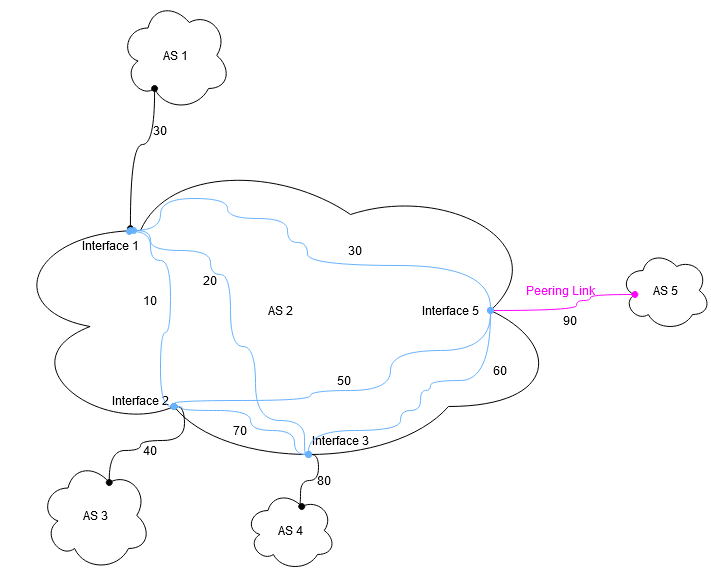
The staticInfoConfig.json configuration file for this AS could then look like this:
{
  "Latency": {
    "1":{
      "Inter": "30ms",
      "Intra": {
        "2": "10ms",
        "3": "20ms",
        "5": "30ms"
      }
    },
    "2":{
      "Inter": "40ms",
      "Intra": {
        "1": "10ms",
        "3": "70ms",
        "5": "50ms"
      }
    },
    "3":{
      "Inter": "80ms",
      "Intra": {
        "1": "20ms",
        "2": "70ms",
        "5": "60ms"
      }
    },
    "5":{
      "Inter": "90ms",
      "Intra": {
        "1": "30ms",
        "2": "50ms",
        "3": "60ms"
      }
    }
  },
  "Bandwidth": {
    "1":{
      "Inter": 400000000,
      "Intra": {
        "2": 100000000,
        "3": 200000000,
        "5": 300000000
      }
    },
    "2":{
      "Inter": 4000000000,
      "Intra": {
        "1": 5044444,
        "3": 6555555550,
        "5": 75555550
      }
    },
    "3":{
      "Inter": 80,
      "Intra": {
        "1": 9333330,
        "2": 10444440,
        "5": 133333310
      }
    },
    "5":{
      "Inter": 120,
      "Intra": {
        "1": 1333330,
        "2": 155555540,
        "3": 15666660
      }
    }
  },
  "Linktype": {
    "1":"direct",
    "2":"opennet",
    "3":"multihop",
    "5":"direct"
  },
  "Geo": {
    "1":{
      "Latitude": 48.858222,
      "Longitude": 2.2945,
      "Address": "Eiffel Tower\n7th arrondissement\nParis\nFrance"
    },
    "2": {
      "Latitude": 48.8738,
      "Longitude": 2.295,
      "Address": "Place Charles de Gaulle\n8th arrondissement\nParis\nFrance"
    },
    "3":{
      "Latitude": 47.22,
      "Longitude": 42.23,
    },
    "5":{
      "Latitude": 48.2,
      "Longitude": 46.2,
    }
  },
  "Hops": {
    "1":{
      "Intra": {
        "2": 2,
        "3": 3,
        "5": 0
      }
    },
    "2":{
      "Intra": {
        "1": 2,
        "3": 3,
        "5": 1
      }
    },
    "3":{
      "Intra": {
        "1": 4,
        "2": 6,
        "5": 3
      }
    },
    "5":{
      "Intra": {
        "1": 2,
        "2": 3,
        "3": 4
      }
    }
  },
  "Note": "GNU Terry Pratchett"
}