SIG (SCION-IP Gateway)
gateway is the SCION-IP Gateway (SIG). It tunnels IP packets over SCION to support communication between hosts that do not natively run SCION. For the protocol specifications, see the IP in SCION Tunneling.
Command Line Reference
Synopsis
gateway [--config <config.toml> | help | version]
Options
- --config <config.toml>
Specifies the configuration file and starts the gateway.
- help, -h, --help [subcommand]
Display help text for subcommand.
- version
Display version information.
- completion [shell]
Generate the autocompletion script for gateway for the specified shell.
Run
gateway help completionfor a list of the available shells.Run
gateway help completion [shell]for usage information on the autocomplete script for a particular shell.
Deployment Examples
Basic SIG Pair
The simplest deployment uses a pair of SIGs to tunnel IP traffic between them. In this example, the two SIGs are respectively in AS 1-ff00:0:110 and AS 1-ff00:0:111.
Each SIG requires two configuration files, with an optional third:
Gateway configuration (
gateway.toml): specifies the gateway id, addresses, and references to the policy files. Generate a starting point withgateway sample config.Traffic policy (
traffic.policy): defines which remote ASes to create tunneling sessions to and what IP prefixes are reachable through them. A minimal traffic policy for AS1-ff00:0:110, declaring that10.2.0.0/24is reachable through AS1-ff00:0:111:{ "ASes": { "1-ff00:0:111": { "Nets": ["10.2.0.0/24"] } }, "ConfigVersion": 1 }
Routing policy (optional): controls which IP prefixes to accept and advertise via SGRP. See Routing Policy File for the full syntax.
The SIG in AS 1-ff00:0:111 needs a matching traffic policy pointing back to AS 1-ff00:0:110 and listing the prefixes reachable through it.
Once both SIGs are running, IP traffic matching the configured prefixes is automatically tunneled over SCION. Each SIG independently discovers remote SIGs via SIG Discovery, fetches their prefix announcements via SGRP, and creates tunneling sessions. Note that path policies for SIGs are not configurable now.
IP traffic must be routed to the SIG using standard IP routing. The SIG automatically installs routes on the machine it runs on, but other hosts in the local network require static routes pointing to the SIG. Dynamic routing mechanisms are not supported.
Multi-SIG Deployment
An AS can run multiple SIGs. Each SIG is configured independently with its own gateway ID, addresses, and policy files.
To hint to remote ASes which SCION interfaces should be used to reach each gateway, use Network prefix pinning. Each gateway can list its preferred interfaces via the allow_interfaces field in the topology file.
Sample Configuration
Generate a sample configuration file with:
gateway sample config > gateway.toml
The sample contains two TOML sections. The key options are summarized below (run the command for the full output with detailed comments):
[gateway]
# ID of the gateway (default "gateway")
id = "gateway"

# The traffic policy file.
# (default "/etc/scion/traffic.policy")
traffic_policy_file = "/etc/scion/traffic.policy"

# The IP routing policy file. If not set, a default policy
# that rejects all IP prefix announcements is used.
# (default "")
ip_routing_policy_file = ""

# The bind address for control messages (SGRP discovery and prefix exchange).
# (default ":30256")
ctrl_addr = ":30256"

# The bind address for encapsulated data traffic.
# (default ":30056")
data_addr = ":30056"

# The bind address for path probes.
# (default ":30856")
probe_addr = ":30856"
id: Identifier for this gateway instance. Relevant when running multiple SIGs.traffic_policy_file: Path to the traffic policy JSON that defines remote ASes and expected prefixes.ip_routing_policy_file: Path to the routing policy that controls prefix acceptance and advertisement via SGRP. If empty, all prefix announcements are rejected.ctrl_addr,data_addr,probe_addr: Bind addresses for the three SIG planes. If the host part is empty, the gateway infers it from the route to the control service.
[tunnel]
# Name of TUN device to create. (default "sig")
name = "sig"

# Source hint for IPv4 routes. (default "")
src_ipv4 = "192.0.2.100"

# Source hint for IPv6 routes. (default "")
src_ipv6 = "2001:db8::2:1"
name: Name of the TUN device the gateway creates. IP packets read from this device are encapsulated and sent over SCION; packets received from SCION are decapsulated and written back to it.src_ipv4,src_ipv6: Source address hints IPv4/IPv6 routes added to the Linux routing table.
Nomenclature
SessionPolicy
A Session Policy describes the traffic configuration to a remote AS. It contains
a Policy ID uniquely identifying the Session Policy
a Traffic Class defining the set of IP packets that are forwarded in this Session
a Path Class defining the set of paths that can be used to forward the IP packets
a Performance Policy defining an ordering on the set of allowed paths with respect to a certain optimization goal
a Path Count defining the number of paths used simultaneously to load balance different flows in the Session
Traffic Class
A Traffic Class defines a classification of IP packets. All IP packets that match the matching criteria of the Traffic Class belong to that class. A Traffic Class has a Name and a Traffic Matcher
Traffic Matcher
A Traffic Matcher defines the matching criteria for a Traffic Class. The matching criteria is defined using the traffic classification language, e.g.,
# match all packets with a dest IP in this prefix
dst=192.168.1.0/24
# match all packets with a given dest IP or given DSCP bits
any(dst=192.168.1.0/24, dscp=0xb2)
Path Class
A Path Class defines a classification of paths. All paths that match the matching criteria of the Path Class belong to that class. A Path Class has a Name and a Path Matcher.
Path Matcher
A Path Matcher defines the matching criteria for a Path Class. The matching criteria is defined using the path policy language, e.g.,
# blacklist paths containing AS 111 (in any ISD). Allow everything else.
acl:
  - 0-111#0
  + 0
# Matches all paths that consisting of any number of interfaces,
# followed by interface 1 in AS 111 followed by at least one other interface.
sequence: 0* 0-111#1 0+
Performance Policy
A Performance Policy defines the performance metric that should be optimized when making a path selection. Possible values can be shortest_path, latency, jitter, droprate, or mix (take a weighted score across all metrics) (note, not all of these are currently implemented and are subject to change). A Performance Policy is used to order the set of paths defined by a Path Class.
Path Count
The Path Count defines the number of paths that can be simultaneously used within a Session. Default is 1.
How it all fits together
A gateway has one or multiple Session Policies per remote AS. The Traffic Class defines the set of IP packets which are forwarded by the configuration. A Path Class defines the set of possible paths that can be used by this configuration. A Performance Policy orders the set of possible paths according to the some metric. Finally, PathCount defines how many paths are being used simultaneously within a configuration.
Port table
Description |
Transport |
Port |
Application protocol |
Control plane |
QUIC/SCION |
30256 |
gRPC (Prefix discovery) |
Probe plane |
UDP/SCION |
30856 |
Custom probe encapsulation |
Underlay data-plane |
UDP/SCION |
30056 |
none |
Monitoring |
TCP |
30456 |
HTTP/2 |
Metrics
Gateway metrics can expose the following set of labels:
remote_isd_as: The ISD-AS of the remote AS.remote_ifid: An interface ID of the remote AS.policy_id: The ID identifying a session policy.
Traffic Metrics
Sent IP packets
Name: gateway_ippkt_bytes_sent_total, gateway_ippkts_sent_total
Type: Counter
Description: Total bytes and packet count of IP packets sent to remote gateways.
Labels: remote_isd_as and policy_id
Received IP packets
Name: gateway_ippkt_bytes_received_total, gateway_ippkts_received_total
Type: Counter
Description: Total bytes and packet count of IP packets received from remote gateways.
Labels: remote_isd_as
Sent local IP packets
Name: gateway_ippkt_bytes_local_sent_total, gateway_ippkts_local_sent_total
Description: Total bytes and packet count of IP packets sent to the local network, i.e., on the internal interface.
Labels: none
Note
In the Anapaya EDGE Gateway this covers only those packets that match one of the configured prefixes.
Received local IP packets
Name: gateway_ippkt_bytes_local_received_total, gateway_ippkts_local_received_total
Description: Total bytes and packet count of IP packets received from the local network, i.e., on the internal interface.
Labels: none
Note
In the Anapaya EDGE Gateway this covers only those packets that match one of the configured prefixes.
Sent frames
Name: gateway_frame_bytes_sent_total, gateway_frames_sent_total
Type: Counter
Description: Total bytes and packet count of frames sent to remote gateways. This counts the frames the gateway uses to encapsulate the IP traffic. A frame can contain a partial, one, or multiple encapsulated IP packets.
Labels: remote_isd_as and policy_id
Received frames
Name: gateway_frame_bytes_received_total, gateway_frames_received_total
Type: Counter
Description: Total bytes and packet count of frames received from remote gateways. This counts the frames the gateway uses to encapsulate the IP traffic. A frame can contain a partial, one, or multiple encapsulated IP packets.
Labels: remote_isd_as
Discarded Frames
Name: gateway_frames_discarded_total
Type: Counter
Description: Counts the number of discarded frames. The reason label can
be used to distinguish different reasons why frames get discarded. Possible values are:
too_old: discarded because the received frame was older than what the receive window allowsinvalid: discarded because the received frame was corruptedduplicate: discarded because the received frame was a duplicateevicted: discarded because a newer frame move the receive window and discarded previously received frames that became too old.
Labels: remote_isd_as, reason
Discarded IP Packets
Name: gateway_ippkts_discarded_total
Type: Counter
Description: Counts the number of discarded IP packets. The reason label
can be used to distinguish different reasons why IP packets get discarded.
Possible values are:
invalid: discarded because the received IP packet was corruptedno_route: discarded because there is no route for the IP packetfragmented: discarded because the IP packet was fragmented.
Labels: reason
I/O errors
Send errors
Name: gateway_send_local_errors_total and gateway_send_external_errors_total
Type: Counter
Description: Counts the number of errors when sending IP packets to the network (LAN) and sending frames to the network (WAN).
Labels: none
Receive errors
Name: gateway_receive_local_errors_total and gateway_receive_external_errors_total
Type: Counter
Description: Counts the number of errors when receiving IP packets from the network (LAN) and receiving frames from the network (LAN).
Labels: none
Path Monitoring Metrics
Monitored paths
Name: gateway_paths_monitored
Type: Gauge
Description: Number of paths being monitored to a given remote AS.
Labels: remote_isd_as
Path probes sent
Name: gateway_path_probes_sent
Type: Counter
Description: Number of path probes being sent.
Labels: remote_isd_as
Path probe replies received
Name: gateway_path_probes_received
Type: Counter
Description: Number of replies to the path probes being received.
Labels: remote_isd_as
Available session paths
Name: gateway_session_paths_available
Type: Gauge
Description: Number of paths to a remote AS per session policy. The
status label indicates the status of the path. Possible values are
rejected alive, and timeout.
Labels: remote_isd_as, policy_id, status
Session Monitoring Metrics
Session probes
Name: gateway_session_probes
Type: Counter
Description: Number of probes sent to a remote AS per session id.
Labels: remote_isd_as, policy_id, session_id
Session probe replies
Name: gateway_session_probe_replies
Type: Counter
Description: Number of probes from a remote AS per session id.
Labels: remote_isd_as, policy_id, session_id
Session is healthy
Name: gateway_session_is_healthy
Type: Gauge
Description: Healthiness flag to a remote AS per session ID. The
session is ephemeral so it is recommended to use after aggregating
per remote_isd_as and policy_id.
Labels: remote_isd_as, policy_id, session_id
Discovery Metrics
Remote gateways
Name: gateway_remotes
Type: Gauge
Description: Number of remote gateways.
Labels: remote_isd_as
Remote IP prefixes
Name: gateway_prefixes_accepted, gateway_prefixes_rejected
Type: Gauge
Description: Number of accepted/rejected remote IP prefixes.
Labels: remote_isd_as
Advertised IP prefixes
Name: gateway_prefixes_advertised
Type: Gauge
Description: Number of advertised IP prefixes.
Labels: remote_isd_as
HTTP API
The HTTP API is exposed by the gateway on the IP address and port of the metrics.prometheus
configuration setting.
The HTTP API does not support user authentication or HTTPS. Applications will want to firewall this port or bind to a loopback address.
In addition to the common HTTP API, the gateway supports the following API calls:
/status(EXPERIMENTAL)Method GET. Prints a text description of the operating state of the Gateway. This includes the list of remote AS numbers, the sessions that exist, what networks are in the routing table. For example, the description might look like the following (note that formatting and contents might change between releases):
ISD-AS 1-ff00:0:111
  SESSION 0, POLICY_ID 0, REMOTE: 172.20.5.6:30856, HEALTHY true
    PATHS:
      STATE REVOKED LATENCY JITTER DROPRATE        PATH
      -->   false      0.47   0.59     0.00        Hops: [1-ff00:0:110 1>1 1-ff00:0:111] MTU: 1472 NextHop: 172.20.4.3:30042

ISD-AS 1-ff00:0:112
  SESSION 1, POLICY_ID 0, REMOTE: 172.20.6.6:30856, HEALTHY true
    PATHS:
      STATE REVOKED LATENCY JITTER DROPRATE        PATH
      -->   false      0.63   0.74     0.00        Hops: [1-ff00:0:110 2>1 1-ff00:0:112] MTU: 1472 NextHop: 172.20.4.5:30042

ISD-AS 1-ff00:0:113
  SESSION 2, POLICY_ID 0, REMOTE: 172.20.7.6:30856, HEALTHY true
    PATHS:
      STATE REVOKED LATENCY JITTER DROPRATE        PATH
      -->   false      0.67   0.51     0.00        Hops: [1-ff00:0:110 1>1 1-ff00:0:111 2>1 1-ff00:0:113] MTU: 1472 NextHop: 172.20.4.3:30042
            false      0.65   0.79     0.00        Hops: [1-ff00:0:110 2>1 1-ff00:0:112 2>2 1-ff00:0:113] MTU: 1472 NextHop: 172.20.4.5:30042


ROUTING TABLE:
172.20.5.0/24 index: 2
  condition: BOOL=true
  session: {ID: 0, path: Hops: [1-ff00:0:110 1>1 1-ff00:0:111] MTU: 1472 NextHop: 172.20.4.3:30042}
172.20.6.0/24 index: 3
  condition: BOOL=true
  session: {ID: 1, path: Hops: [1-ff00:0:110 2>1 1-ff00:0:112] MTU: 1472 NextHop: 172.20.4.5:30042}
172.20.7.0/24 index: 1
  condition: BOOL=true
  session: {ID: 2, path: Hops: [1-ff00:0:110 1>1 1-ff00:0:111 2>1 1-ff00:0:113] MTU: 1472 NextHop: 172.20.4.3:30042}
/engine(EXPERIMENTAL)Method GET. Prints a text description of the full state of the forwarding engine of the Gateway. This includes session health, available paths, session configs, the control-plane routing and the data-plane routing table.
/sessionconfigurator(EXPERIMENTAL)Method GET. Prints a text description of the last input and output of the session configurator.
/ip-routing/policy(EXPERIMENTAL)Method GET. Prints the current routing policy.
Method PUT. Updates the current routing policy. This can be used instead of forcing a reload from disk via
SIGHUP. Only the routing policy is reloaded, and the update only affects the in-memory state of the gateway (in other words, the gateway does not write the configuration it has received to disk, so a restart will cause the changes to be overwritten by whatever is on disk).
/configversion(EXPERIMENTAL)Method GET. Prints the version number of the traffic policy configuration file.
Routing Policy File
The routing policy file contains the configuration which IP prefixes are advertised, accepted, and rejected.
A routing policy consists of a list of rules. Each rule consists of an action and three matchers. Optionally, a rule can have a comment.
Policies are defined in plain text. Each line represents a rule. Each rule consists of four whitespace separated columns. The optional comment is appended at the end of the line and needs to start with a ‘#’.
accept     1-ff00:0:110   1-ff00:0:112  10.0.1.0/24,10.0.2.0/24  # Accept from AS 110.
accept     2-0            1-ff00:0:112  10.0.3.0/24              # Accept from ISD 2.
reject     !1-ff00:0:110  1-ff00:0:112  10.0.0.0/8               # Reject unless AS 110.
advertise  1-ff00:0:112   1-ff00:0:110  10.0.9.0/8               # 1-ff00:0:112 advertises 10.0.9.0/8 to 1-ff00:0:110.
The first column represents the action. Currently, we support:
accept    <a> <b> <prefixes>: <b> accepts the IP prefixes <prefixes> from <a>.
reject    <a> <b> <prefixes>: <b> rejects the IP prefixes <prefixes> from <a>.
advertise <a> <b> <prefixes>: <a> advertises the IP prefixes <prefixes> to <b>.
The remaining three columns define the matchers of a rule. The second and third column are ISD-AS matchers, the forth column is a prefix matcher.
The second column matches the ‘from’ ISD-AS. The third column the ‘to’ ISD-AS. ISD-AS matchers support wildcards and negation:
1-ff00:0:110   Matches for 1-ff00:0:110 only.
0-ff00:0:110   Matches for all ASes with AS number ff00:0:110.
1-0            Matches for all ASes in ISD 1.
0-0            Matches for all ASes.

!0-ff00:0:110  Matches for all ASes except the ones with AS number 'ff00:0:110'.
!1-ff00:0:110  Matches for all ASes except 1-ff00:0:110.
!1-0           Matches for all ASes not in ISD 1.
Network prefix matcher consist of a list of IP prefixes to match. The list is comma-separated. A prefix matches, if it is in the subset of the union of the IP prefixes in the list. The network prefix matcher can also be negated. The negation applies to the entire list. A prefix matches in the negated case, if it is not a subset of the union of the prefix list.
10.0.1.0/24,10.0.2.0/24    Matches all IP prefixes that are a subset of 10.0.1.0/24 or
                           10.0.2.0/24. It also matches 10.0.1.0/24 and 10.0.2.0/24.
!10.0.1.0/24,10.0.2.0/24   Matches all IP prefixes that are not a subset of 10.0.1.0/24 and
                           not a subset of 10.0.2.0/24.
Next-Hop Tracking
This is an Anapaya only feature.
The advertise action supports an additional, optional argument:
advertise <a> <b> <prefixes> [<next-hop>]
If next-hop IP address is specified, the prefixes are advertised only if that address is responding to pings. This allows to retract a set of prefixes dynamically without having to resort to BGP.
Default Routing Policy
The routing policy file is optional. If no routing policy is explicitly defined, the gateway uses a default policy equivalent to
reject 0-0 0-0 0.0.0.0/0,::/0
i.e., it rejects all IP prefixes advertised by any remote. Additionally, no local
IP prefixes are advertised, because there is no explicit advertise directive.
Network prefix pinning
When a SCION Gateway sends data to a remote SCION Gateway, it does so based on the policies that are configured locally and the prefixes it learns from the remote gateway. When multiple remote gateways are available, the choice of gateway and path is completely in the hands of the sending AS.
However, in some scenarios the remote AS might be composed of multiple data centers, and might want to avoid traffic between the data centers. To do this it can use a feature called Prefix pinning, which allows a remote AS to hint at how traffic should be sent towards it. In this section we outline when Gateway pinning is relevant, and how to configure it.
Refer to the topology below. New Zealand is the local AS, and it contains one
IPv4 network: 10.0.2.0/24. This network wants to communicate with two
networks in the Australia AS, 192.168.1.0/24 and 192.168.2.0/24. The
networks are reachable through either the Perth Router (Interface ID 101) or
the Melbourne Router (Interface ID 201), and then, depending on the
destination network, through either the Perth Gateway or Melbourne Gateway.
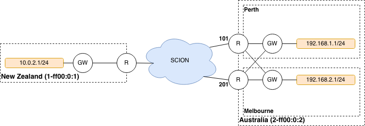
It is possible for traffic to flow from the Perth Router to the Melbourne Gateway. This can happen if the New Zealand gateway chooses to encapsulate traffic for the Melbourne gateway but chooses a path going through the Perth router.
The networking administrators of the Australia AS want to prohibit this
behavior because it would lead to increased latency and an inefficient use of
inter-DC bandwidth. Instead, 192.168.1.0/24 should only be reachable
through the Perth Router and Gateway, and 192.168.2.0/24 should only be
reachable through the Melbourne Router and Gateway.
We’ll first look at how the basic configuration for dynamic prefix discovery for the Perth and Melbourne gateways would look like, and then see why it is not sufficient to provide the connectivity constraints the Australia AS administrators want.
To configure dynamic prefix discovery, Australia configures its gateways with the following traffic policies:
# Perth
advertise 2-ff00:0:2 1-ff00:0:1 192.168.1.0/24
accept           0-0        0-0      0.0.0.0/0

# Melbourne
advertise 2-ff00:0:2 1-ff00:0:1 192.168.2.0/24
accept           0-0        0-0      0.0.0.0/0
This will have the gateways advertise the two internal networks in Australia, and the New Zealand gateway will thus learn the prefixes and be able to route to them. For completeness, the New Zealand gateway might have the following configuration:
# New Zealand
advertise 1-ff00:0:1 2-ff00:0:2 10.0.2.0/24
accept           0-0        0-0   0.0.0.0/0
Assuming routing inside the two ASes is configured correctly, hosts in
10.0.2.0/24 should now be able to ping hosts in 192.168.1.0/24 and
192.168.2.0/24.
However, when New Zealand chooses paths for reaching the gateways in Australia, it does so independently of the remote gateways. This is because the internal structure of the Australia AS is hidden from New Zealand, so it cannot make assumptions about what paths would be more appropriate for each gateway. In total, there are four possible combinations:
Perth Router (Interface ID 101) to Perth Gateway (for destination
192.168.1.1).Perth Router (Interface ID 101) to Melbourne Gateway (for destination
192.168.2.1).Melbourne Router (Interface ID 201) to Perth Gateway (for destination
192.168.1.1).Melbourne Router (Interface ID 201) to Melbourne Gateway (for destination
192.168.2.1).
For Australia to recommend that New Zealand use only options 1 and 4, it needs an additional config.
Path pinning is a Discovery Service setting that informs the Discovery Service to hint to other ASes which SCION Interfaces should be used to reach a gateway. The setting is configured via the topology file.
In this scenario, Australia can configure the topology file as follows:
{
  "sigs": {
    "perth": {
      "ctrl_addr": "...omitted...",
      "data_addr": "...omitted...",
      "allow_interfaces": [
        101
      ]
    },
    "melbourne": {
      "ctrl_addr": "...omitted...",
      "data_addr": "...omitted...",
      "allow_interfaces": [
        201
      ]
    }
  }
}
Due to the additional allow_interfaces setting, the Discovery Service in
the Australia AS will announce that the respective gateways should be
reachable only through the specified interface. Note that this is only a
hint. In the end, the New Zealand AS can choose to ignore this setting, and
still send data to the Melbourne network via the Perth router. However,
Anapaya software will respect the hint.
Multiple interfaces can be specified in allow_interfaces, and the same
interface can be present under multiple gateways.
Configuration
In addition to the common .toml configuration options, the gateway service considers the following options.